
Week -7: Computer Controlled Machining
During week -7, the focus is on computer controlled machining. This involves understanding the principles of Computer Numerical Control (CNC) and how it applies to various machining techniques. Students will get hands-on experience with a range of CNC machines, allowing them to turn digital designs into physical objects. They will also learn about the safety procedures necessary when working with these machines. By the end of the week, students should be comfortable with operating a CNC machine and be familiar with the process of taking a design from concept to completed product.
Group Assignment:
- Complete your lab's safety training
- Test runout, alignment, fixturing, speeds, feeds, materials, and toolpaths for your machine
- Link for group Assignment - Link
Individual Assignment:
- Design, mill, and assemble something large (~meter-scale)
Extra Credit:
- Don't use fasteners or glue
- Include curved surfaces
Concept Sketch:
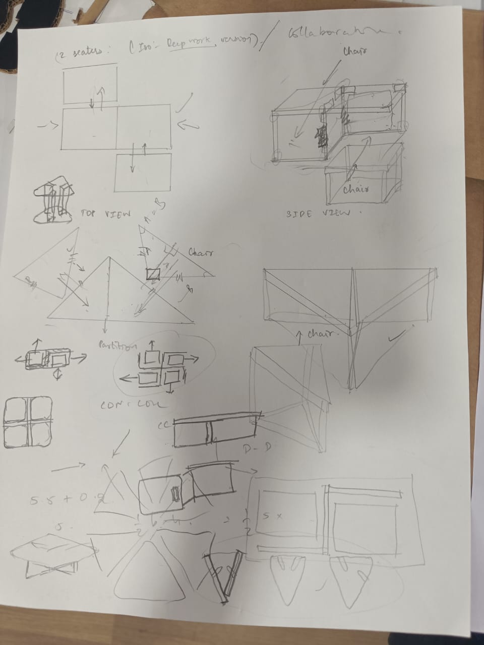
Description:
- Triangle Table Design : The table is designed in a triangular shape to accommodate three chairs, promoting equal participation and interaction among users.
- Convergent Placement : The chairs are positioned facing each other, encouraging collaboration and discussion. This arrangement fosters brainstorming sessions, group meetings, or casual conversations.
- Compact Design : The compact size of the furniture ensures that it occupies minimal space in the room. When not in use, the chairs can be tucked neatly under the table, saving floor space and maintaining a clutter-free environment.
- Functional Tabletop : The tabletop provides ample space for placing laptops, documents, or other work materials, catering to the needs of collaborative and individual tasks.
- Comfortable Seating : The chairs are ergonomically designed to ensure comfort during extended periods of sitting, enhancing productivity during collaborative or focused work sessions.
Benefits of Space-Efficient Furniture:
- Maximizes Floor Space : In environments where space is limited, such as small offices or coworking spaces, compact furniture helps maximize available floor space. This allows for better utilization of the area without overcrowding.
- Enhances Mobility : Lightweight and easily movable furniture enable users to rearrange the layout according to their needs. Whether it's reconfiguring for a group activity or creating individual workstations, space-efficient furniture offers flexibility.
- Promotes Organization : By reducing clutter and optimizing space, compact furniture contributes to a more organized and visually appealing environment. This, in turn, can positively impact productivity and creativity.
- Adaptable to Changing Needs : As work dynamics evolve, versatile furniture adapts to varying requirements. Whether it's accommodating a team meeting or providing quiet space for focused work, adaptable designs cater to diverse needs effectively.
- Cost-Effective Solution : Investing in space-efficient furniture can be a cost-effective solution for businesses and individuals alike. With its ability to serve multiple functions and optimize space usage, it offers long-term value and efficiency.
By integrating convergent and divergent placement principles into furniture design, along with prioritizing space efficiency, this concept promotes a dynamic and adaptable workspace conducive to both collaborative endeavors and individual productivity.
Steps used for designing table and chair using fusion 360:
Step 1: Set Up the Project:
- Launch Fusion 360 and create a new project.
- Create a new design and save it with an appropriate name.
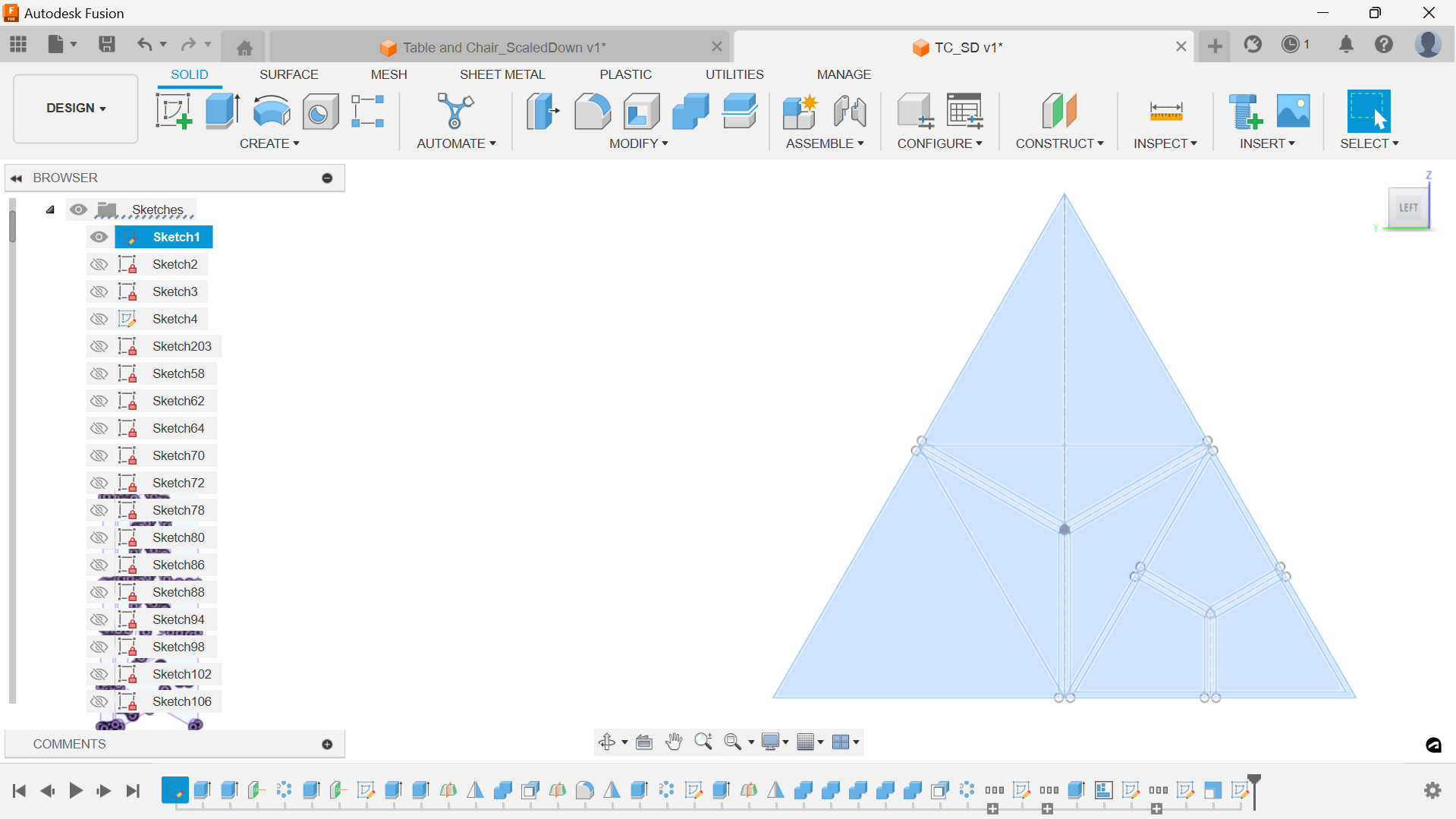
Step 2: Create the Table:
- Start by creating a new sketch on the XY plane.
- Use the Polygon tool to draw a triangle, specifying the dimensions of the sides according to your desired table size.
- Extrude the sketch to create the table's top surface to the desired thickness.
- Create another sketch on one of the triangular faces of the table.
- Use the Offset tool to create a smaller triangle inside the previous one, representing the space for the stools to fit.
- Extrude the inner triangle downwards to create a cavity inside the table.
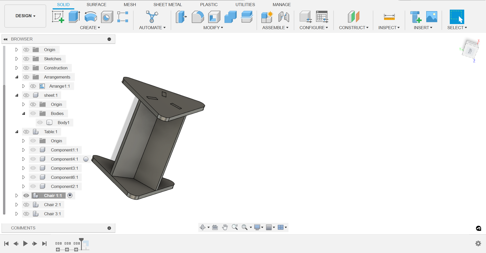
Step 3: Create the Stools:
- Start a new sketch on the XY plane.
- Draw a triangle representing the stool's seat, ensuring it fits inside the cavity of the table.
- Extrude the sketch to create the seat thickness.
- Create another sketch on one of the stool's triangular faces.
- Draw a smaller triangle inside the previous one, representing the legs of the stool.
- Extrude the inner triangle downwards to create the stool's legs.
Step 4: Stackable Design:
- Ensure the dimensions of the stools allow them to stack neatly inside the table's cavity.
- Adjust the height of the stools if necessary to ensure they fit without interference.
- Ensure that the top of the stools is flush with the table's surface when stacked inside.
Step 5: Final Touches:
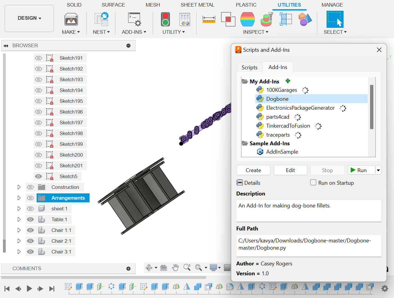
- Add any additional features or details to the table and stools, such as chamfers or fillets, to improve aesthetics and functionality. Here, I have added dogbones using the plugin available from this link .
Adding dogbones using the plugin after selecting all the edges with 6.1 mm.
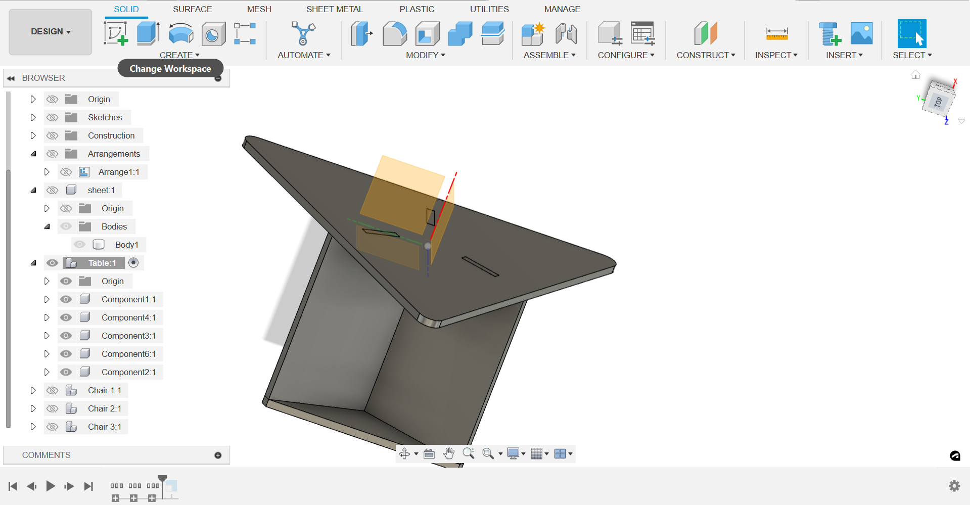
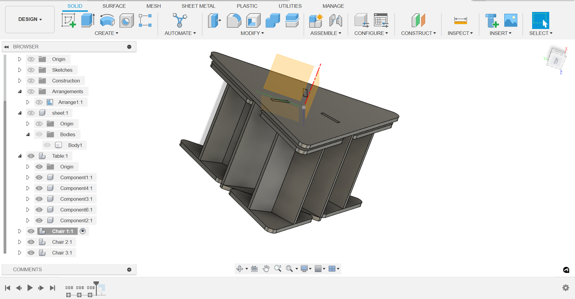
Step 6: Assembly:
- Use the Assemble tool to bring together the table and stools within the Fusion 360 environment.
- Position the stools inside the table's cavity to ensure they fit properly and are aligned correctly.
- Check for any interference or overlapping parts and make adjustments as necessary.
- Once satisfied with the assembly, save the final design.
Step 7: Documentation:
- Create 2D drawings or renderings of the final design to document and communicate the project.
- Include dimensions, materials, and any other relevant information in the documentation.
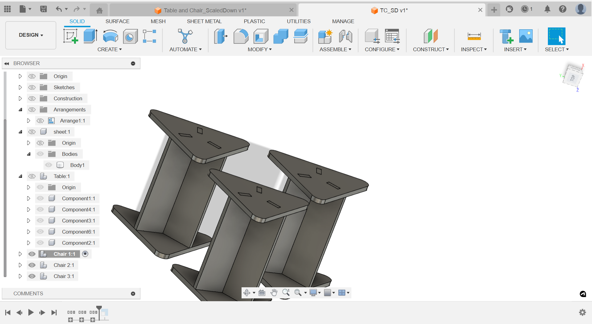
I created a sketch of a triangular table top of 3 ft and extensions to connect as small circular patterns and a chair using the same procedure.
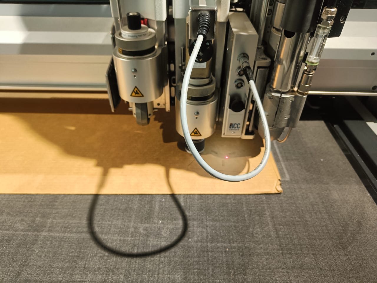
Using Zund Machine for carboard model scaled down to 1/6th of the original size:
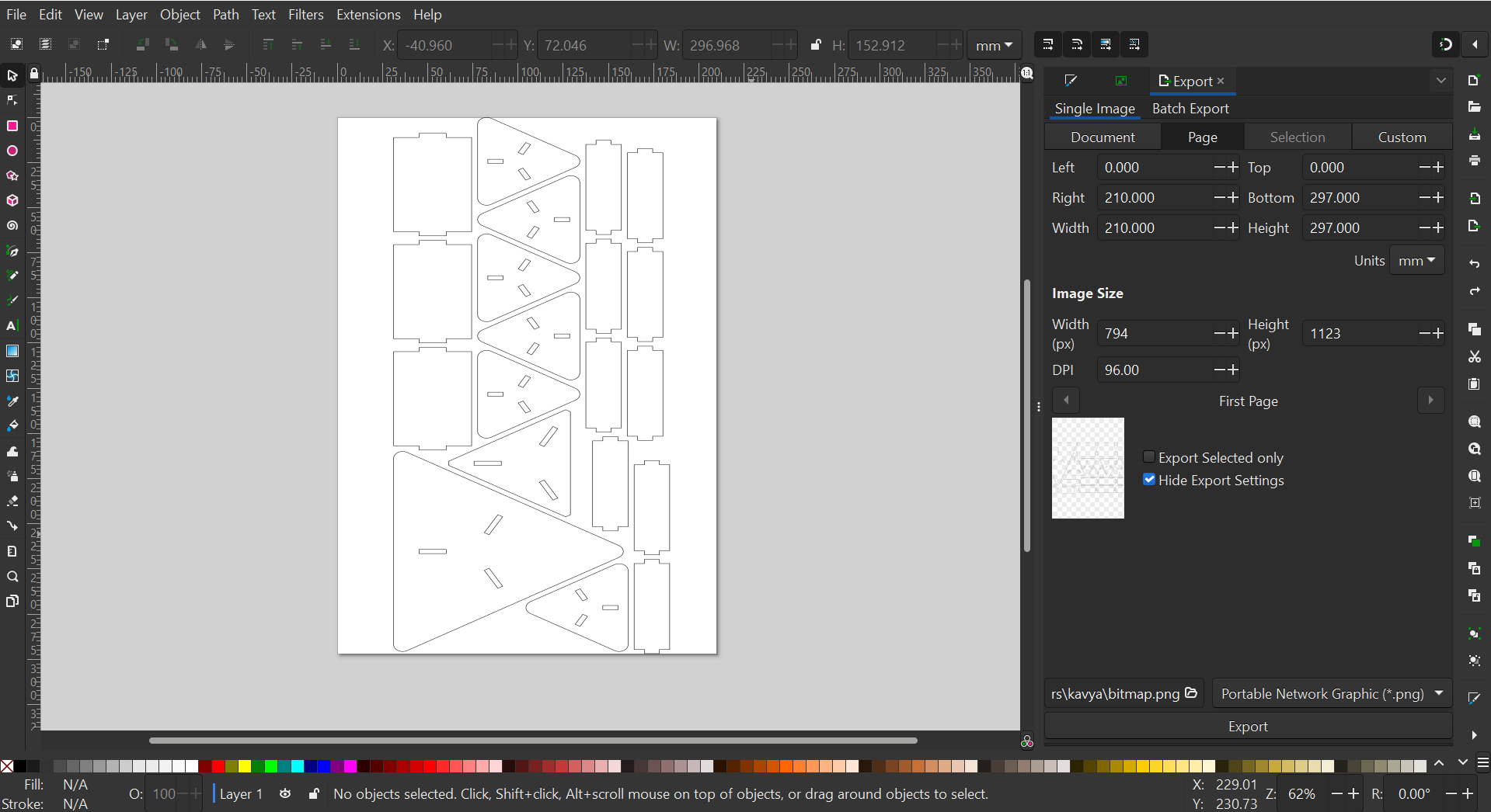
Step 1: Prepare the DXF File:
- Open your DXF file in a CAD software to review and ensure it is correctly scaled and ready for cutting.
- Save the file in a location accessible to the Zund machine's software.
Step 2: Load Material onto the Zund Machine:
- Place the B-flute cardboard sheet onto the Zund machine's cutting bed. Make sure the sheet is aligned straight with the edges of the bed.
- Use the vacuum function if available to secure the cardboard to the bed.
Step 3: Set Up the Machine:
- Turn on the Zund machine and open the Zund Cut Center software.
- Select the correct cutting tool (knife) for B-flute cardboard. Consult the machine's manual or seek professional advice if unsure.
- Perform a test cut if necessary to ensure the knife is sharp and the cutting pressure is correct.
Step 4: Import the DXF File:
- In the Zund Cut Center software, click on the "Import" button and navigate to the location of your saved DXF file.
- Select your file and click "Open". The file should now appear in the software.
Step 5: Set Cutting Parameters:
- Select the file in the Zund Cut Center software and open the cutting parameters dialog.
- Set the cutting speed, pressure, and tool type according to the specifications for B-flute cardboard. This information may be available in the Zund machine's manual or can be obtained from a professional.
Step 6: Start Cutting:
- Once the cutting parameters are set, click on the "Start" button in the Zund Cut Center software.
- Monitor the machine while it is cutting to ensure it is operating correctly and safely.
Step 7: Unload the Cut Cardboard:
- Once the machine has finished cutting, turn off the vacuum function (if used) and carefully remove the cut cardboard from the machine's bed.
- Check the cut pieces for accuracy and quality.
Step 8: Clean Up:
- Dispose of any waste material properly.
- Clean the Zund machine and cutting bed according to the manufacturer's instructions.
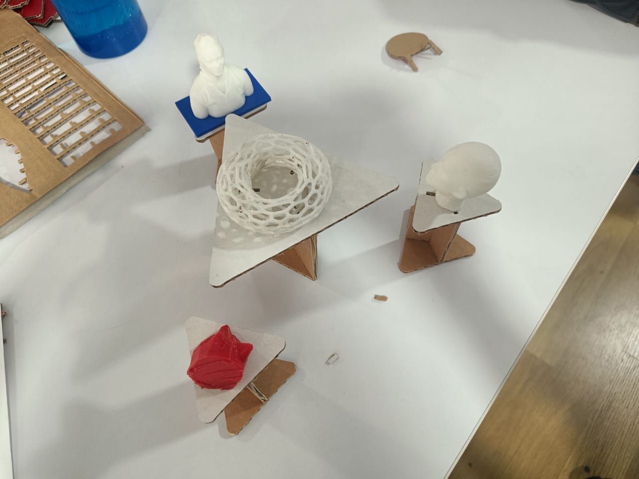
Assembled model:
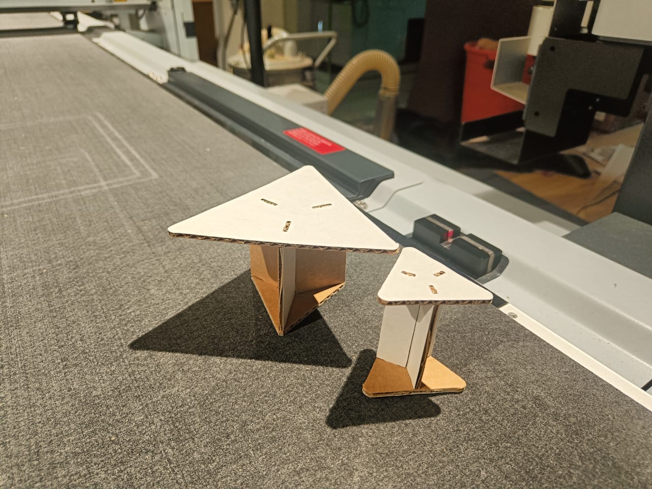


Here’s the assembly of the donut party I had set up for our 3D printed designs on my table.
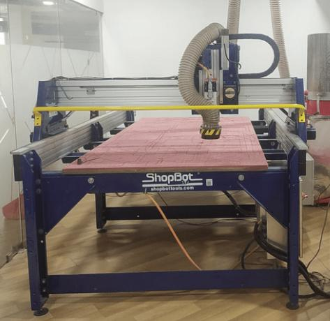
About ShopBot3:
ShopBot3, often referred to as just ShopBot, is a robust, high-performance Computer Numerical Control (CNC) router. It is used for precision cutting, carving, drilling, and machining of a wide variety of materials. This includes wood, MDF, plastics, foams, vinyl, and aluminum among others.
This machine is popular due to its versatility and reliability. It can handle small-scale, intricate designs as well as large, heavy-duty tasks, making it a favorite tool among carpenters, engineers, and designers. ShopBot3 is often used in industries such as furniture manufacturing, sign making, mold making, aerospace, and marine applications.
Its CNC capabilities mean that designs created in CAD (Computer-Aided Design) software can be directly imported into the ShopBot software. The machine then accurately executes these designs, allowing for a high level of detail and precision. This automation not only increases efficiency but also reduces the chance of human error.
Another key advantage of ShopBot3 is its user-friendly software. The software is designed to be intuitive, making it easier for users to operate the machine, even with little previous experience.
Overall, ShopBot3 is a valuable addition to any workshop due to its capabilities, flexibility, and user-friendly interface.
ShopBot in our lab:
Safety Precautions:
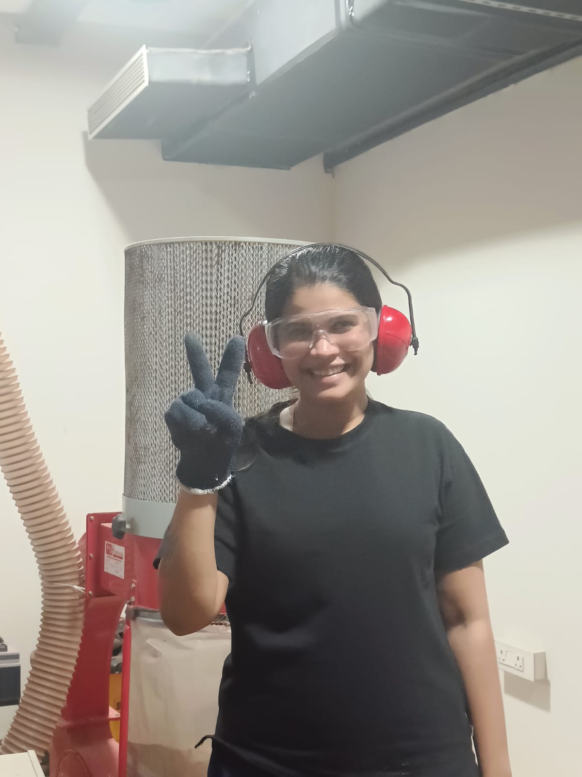
Safety is paramount when working with machinery like the ShopBot3. Here are some important safety precautions to keep in mind:
- Proper Training : Make sure you are properly trained on how to use the ShopBot3. Never attempt to use the machine without the necessary training and understanding of its operation.
- Use Safety Gear : Always wear appropriate safety gear when operating the machine. This includes safety glasses to protect your eyes from debris, ear protection to guard against noise, and dust masks or respirators if working with materials that produce dust or fumes.
- Check the Machine Before Use : Always inspect the machine before starting. Make sure all parts are in good working condition and that the machine is clean and free of debris.
- Secure Materials Properly : Ensure that the material you are working on is properly secured to the machine bed. Loose materials can cause accidents and damage the machine.
- Keep a Safe Distance : Stay a safe distance away from the machine while it is in operation. Never place your hands or any other body parts near the cutting area.
- Don't Leave the Machine Unattended : Never leave the machine running unattended. If you need to step away, always pause or stop the machine first.
- Know How to Stop the Machine : Make sure you know how to stop the machine in case of an emergency. Familiarize yourself with the locations of the emergency stop buttons.
- Follow the Software Guidelines : Always follow the software guidelines when creating and executing tool paths. Incorrect settings can result in dangerous machine behavior.
- Maintenance : Regular maintenance is key to safe operation. Keep the machine clean, lubricate moving parts as instructed in the machine manual, and regularly check for wear and tear.
- Report Problems : If you notice any problems with the machine, report them to a supervisor or a maintenance technician immediately. Do not attempt to fix any problems yourself unless you are qualified to do so.
VCarve Pro
VCarve Pro is a powerful and flexible software solution for CNC routing, carving, and engraving. It provides a robust but intuitive software solution for creating and cutting parts on a CNC Router. This software is commonly used for the manufacturing of decorative panels and doors, ornamental flourishes, custom millwork, architectural moldings, dimensional signage, carved company logos, custom gifts, and awards, and more.
Features of VCarve Pro:
- 2D Design and Layout Tools : VCarve Pro provides a full set of drawing and editing tools to create complex designs. It also provides options to import 2D designs from other software.
- 3D Import and Assembly : This feature allows importing 3D models and assembling them for 2D and 3D toolpath creation.
- Toolpath Creation : VCarve Pro provides options for creating a variety of toolpaths, including profiling, pocketing, drilling, inlays, and prism carving. These toolpaths can be optimized for efficient and effective cutting.
- Material Setup : Users can define material dimensions, zero positions, and tool information in the material setup panel.
- Layer Management : VCarve Pro offers features for layer management, allowing for organizing and controlling the visibility of vectors during the design process.
- Text Tools : The software provides comprehensive text creation and editing tools, making it easy to create engraved signage or artistic text.
Using VCarve Pro for Developing a Layer by Layer Cutting Workflow:
VCarve Pro's layer management and toolpath creation features make it ideal for developing a layer by layer cutting workflow. Here's how:
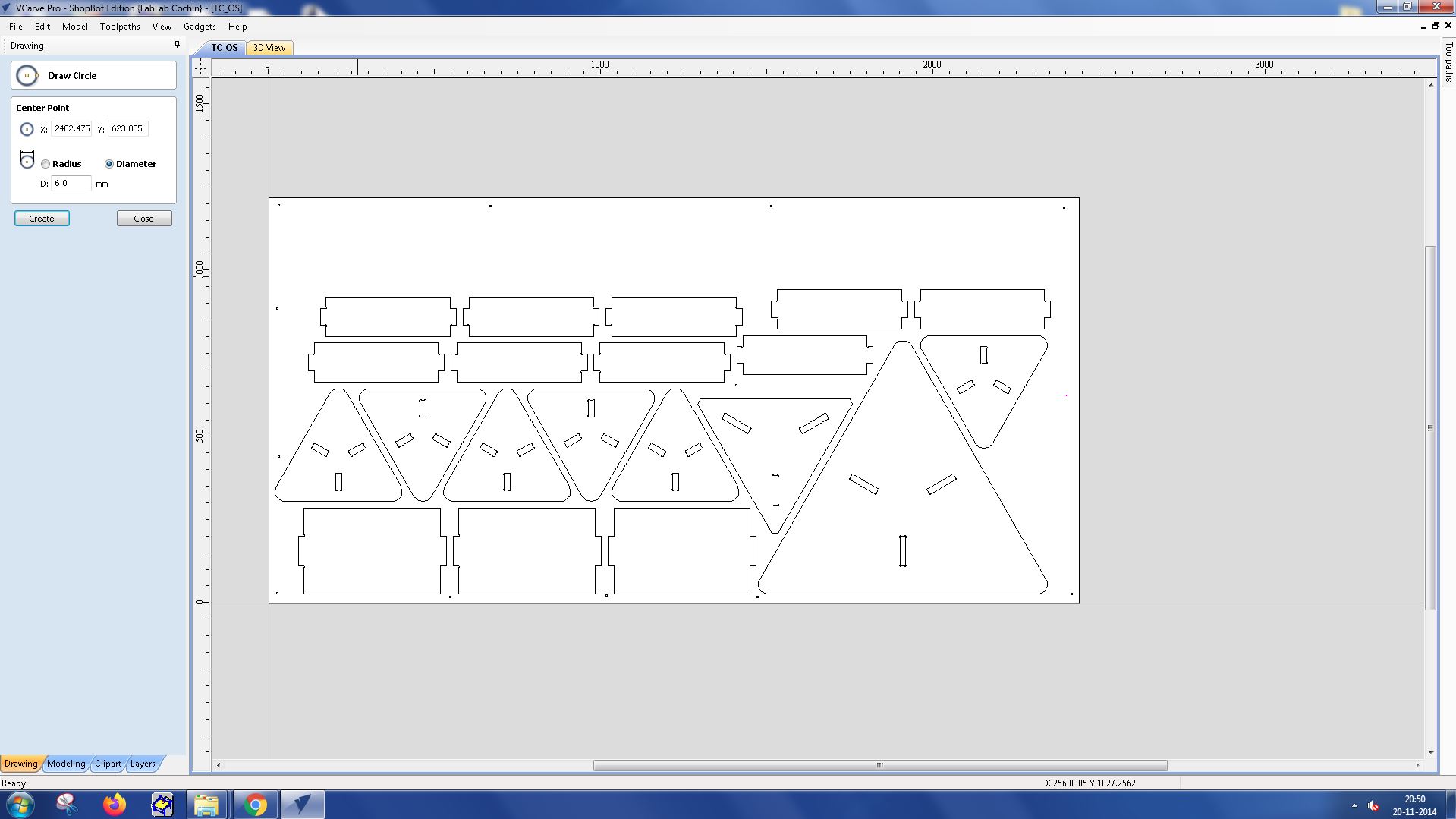
Design Creation : Create or import your design in VCarve Pro. Use the software's powerful 2D and 3D design tools to refine and customize your design.
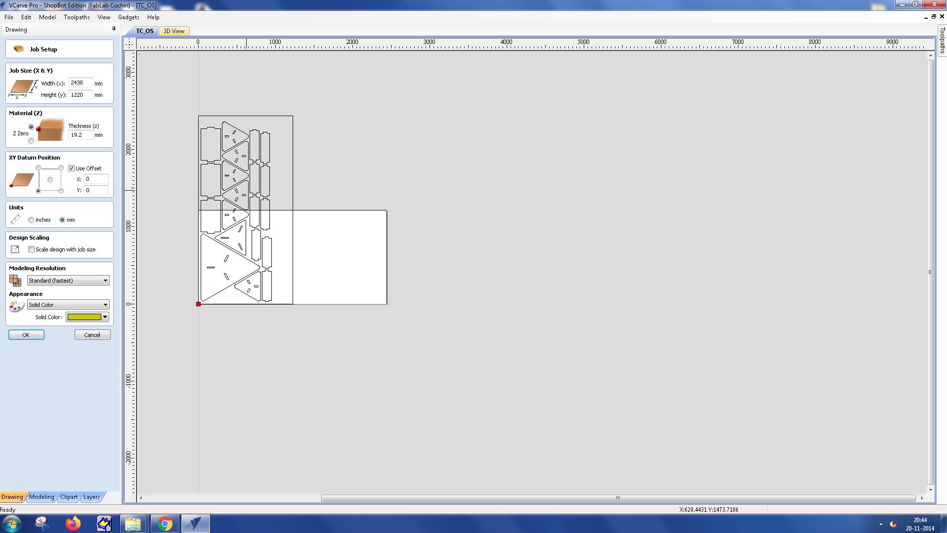
Job size was set as (x,y) - (2438.4, 1220)
Material thickness was set as 19.2 mm as the highest thickness in the job was 19.2 mm.
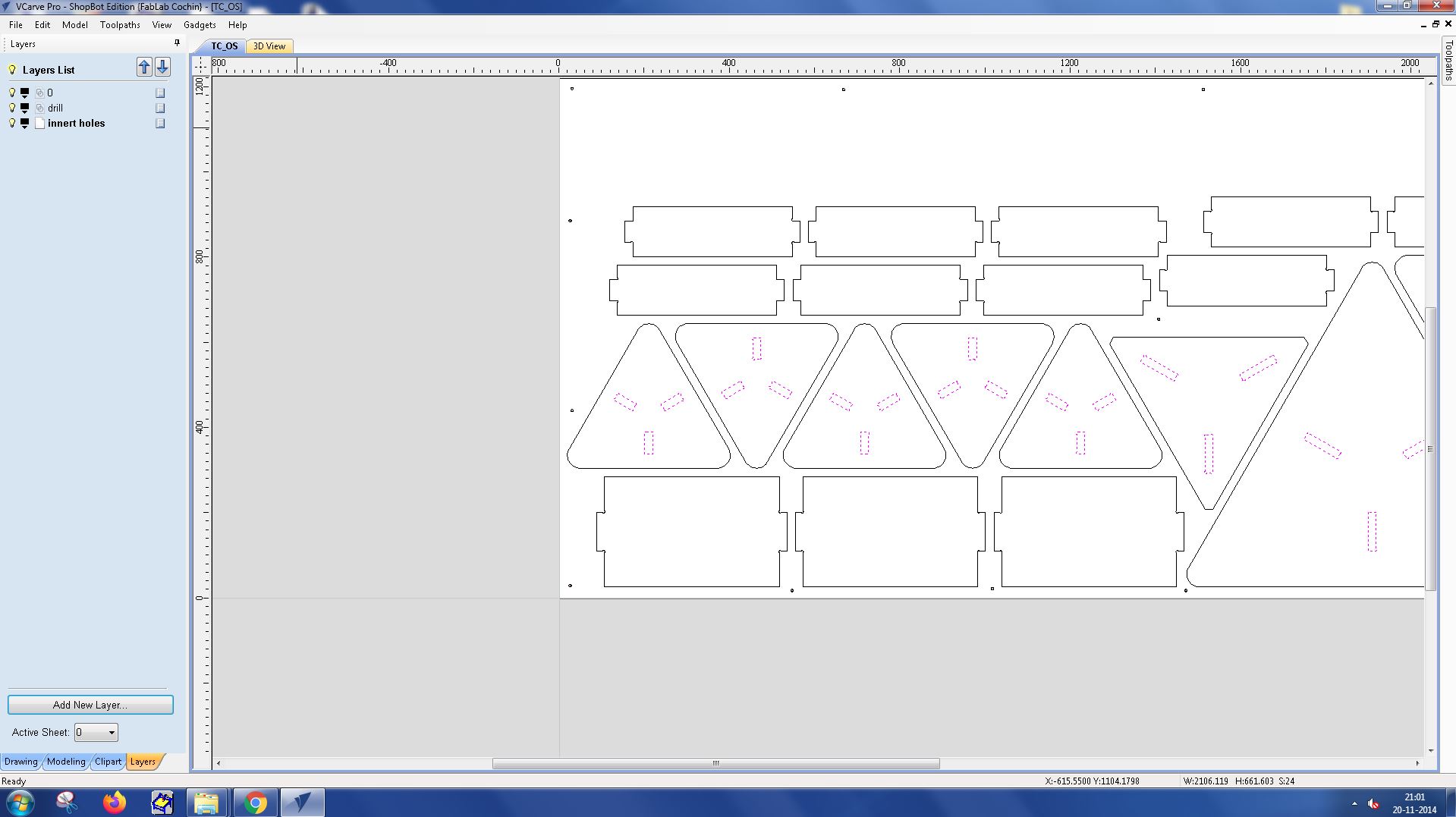
Layer Management : Organize your design into layers. Each layer can represent a different depth of cut, allowing you to plan your cutting process in a structured way.
Toolpath Creation : For each layer, create a separate toolpath. This allows you to control the cutting process for each layer individually, optimizing for the best cutting results.
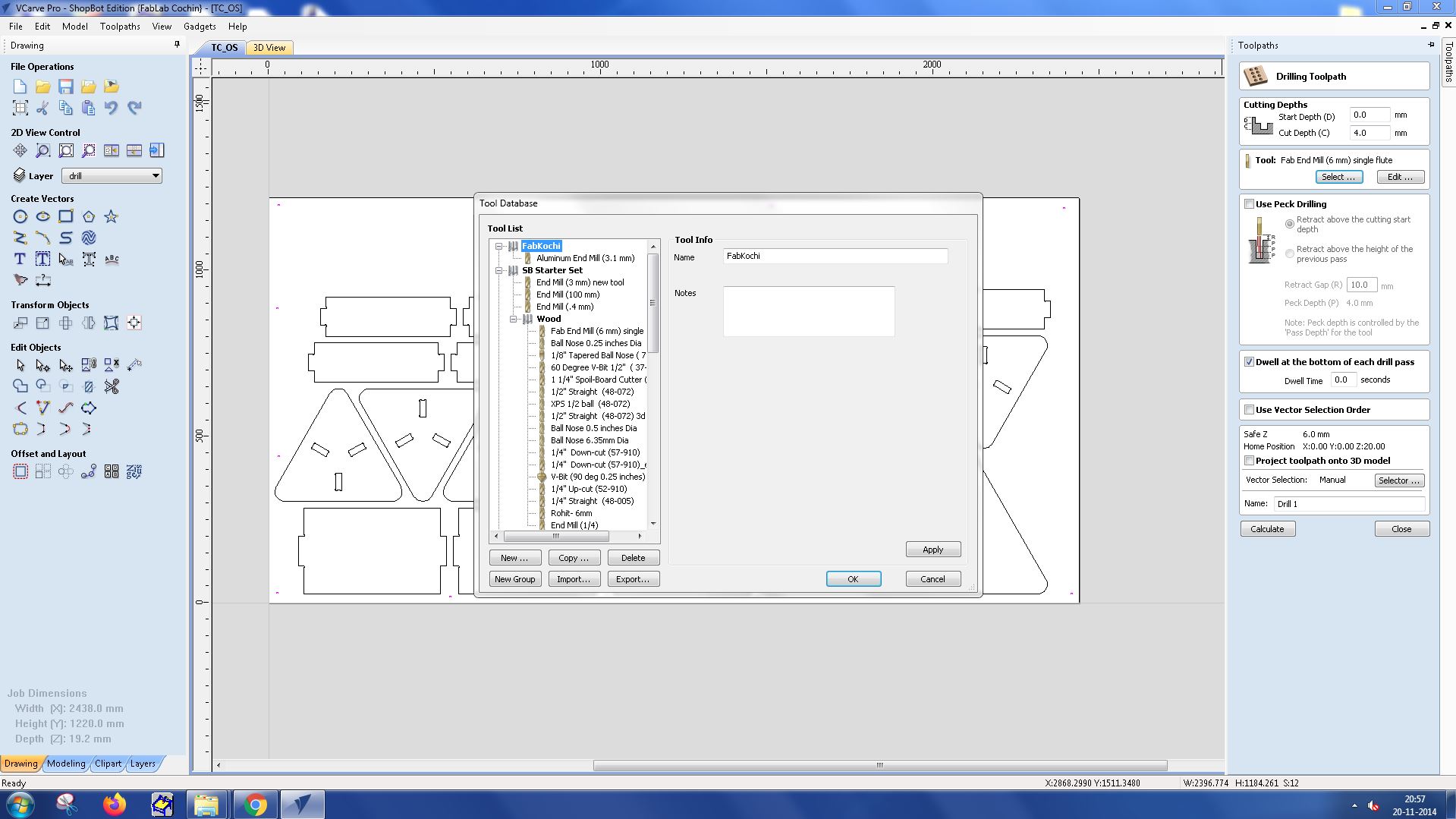
I selected the tool Fab Endmill 6mm from the tool database.
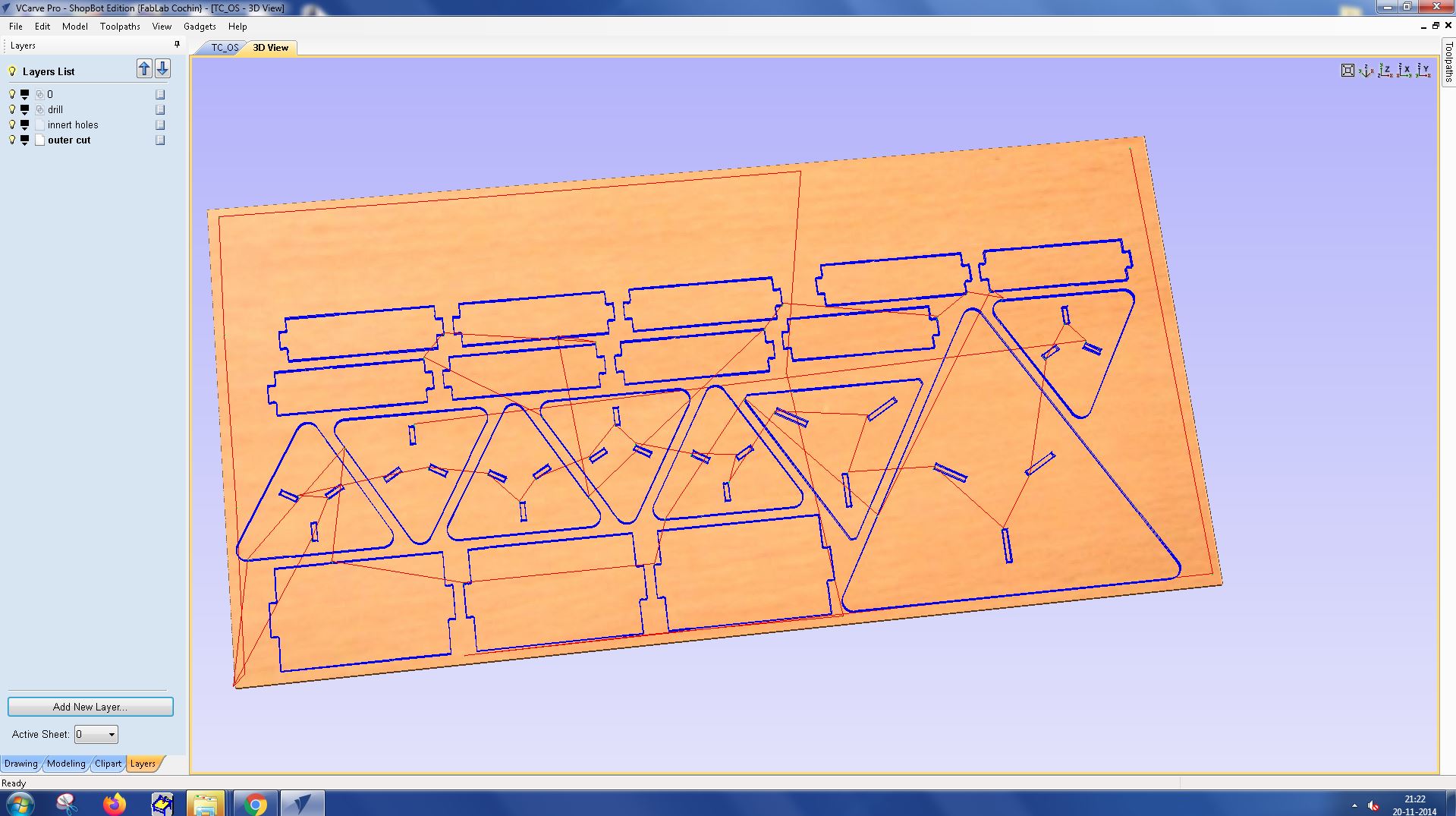
Toolpath was created for all the layers and the following was the result of it.
Material Setup : Define the material setup for each layer, specifying the dimensions, zero positions, and tool information.
Cutting the Design : Export the toolpaths and use them to cut your design on a CNC router layer by layer. This process allows for precise control over the cutting depth and other parameters for each layer.
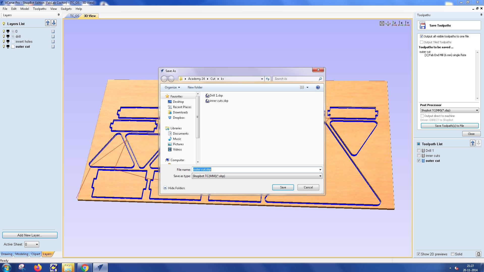
Cutting files were generated and saved systematically.
With VCarve Pro, you can create complex, layered designs and cut them with precision, achieving excellent results.
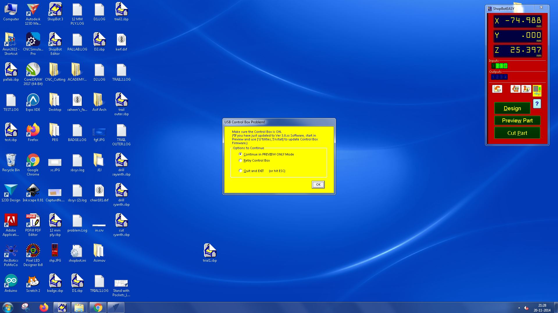
ShopBot3 Interface and Features:
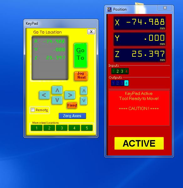
ShopBot3 features a user-friendly interface that allows operators to control and monitor the machine's operations. The interface displays the X, Y, and Z coordinates of the machine's cutting head, providing real-time feedback during cutting operations. It also provides controls for setting the machine's speed, power, and other parameters.
The interface also includes a visual preview of the cutting path, which helps operators confirm the operation before starting the actual cutting process. This feature helps reduce errors and saves time and materials.
How to Use ShopBot3:
- Start the ShopBot3 Software: Launch the ShopBot3 software on the connected computer.
- Open the Design File: Click on the 'File' menu and select 'Open'. Navigate to your design file and click 'Open'.
- Preview the Cutting Path: Use the visual preview feature to verify the cutting path. Make any necessary adjustments to the design or cutting parameters.
- Set the Cutting Parameters: Enter the desired speed, power, and other parameters for the cutting operation.
Setting Zero:
Before starting the cutting operation, it's crucial to set the zero point for the machine. This point typically corresponds to the top surface of the material you're cutting. Here's how to do it:
- Move the Cutting Head: Use the software controls to move the cutting head to the desired zero point on the material.
- Set the Zero Point: Once the cutting head is in position, click on the 'Zero' button in the software to set the current position as the zero point.
Adding Cutting Files for Cutting Operation:
- Create or Import the Cutting File: Create a new cutting file in a CAD or CAM software, or import an existing file. The file should include the design you want to cut and the cutting path for the machine to follow.
- Save the Cutting File: Save the cutting file in a format compatible with the ShopBot3 software. Common formats include .dxf and .sbp.
- Add the Cutting File to ShopBot3: In the ShopBot3 software, click on the 'File' menu, select 'Open', and navigate to your saved cutting file. Click 'Open' to add the file to the software.
- Set the Cutting Parameters: Before starting the cutting operation, set the desired speed, power, and other parameters in the software.
- Start the Cutting Operation: Once everything is set up, click on the 'Start' button in the software to begin the cutting operation. Monitor the machine throughout the operation to ensure everything runs smoothly.
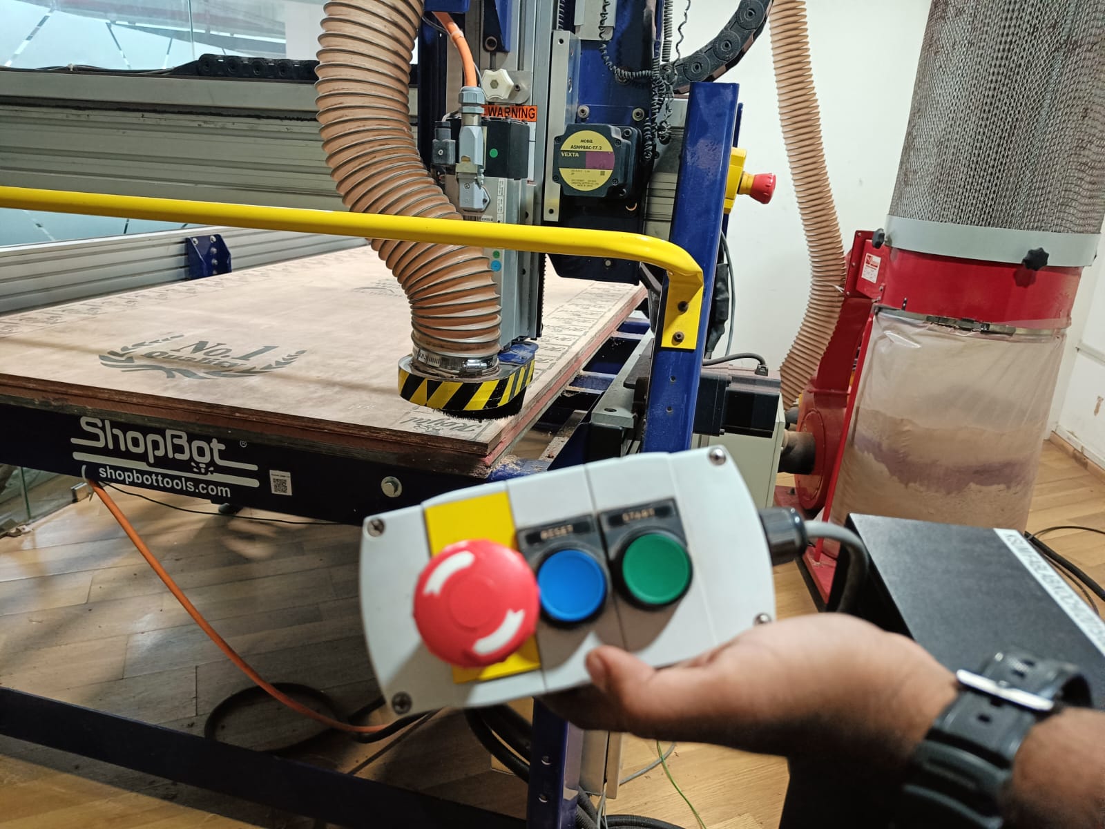
I turned on the spindle key and the control and started the cutting operation.
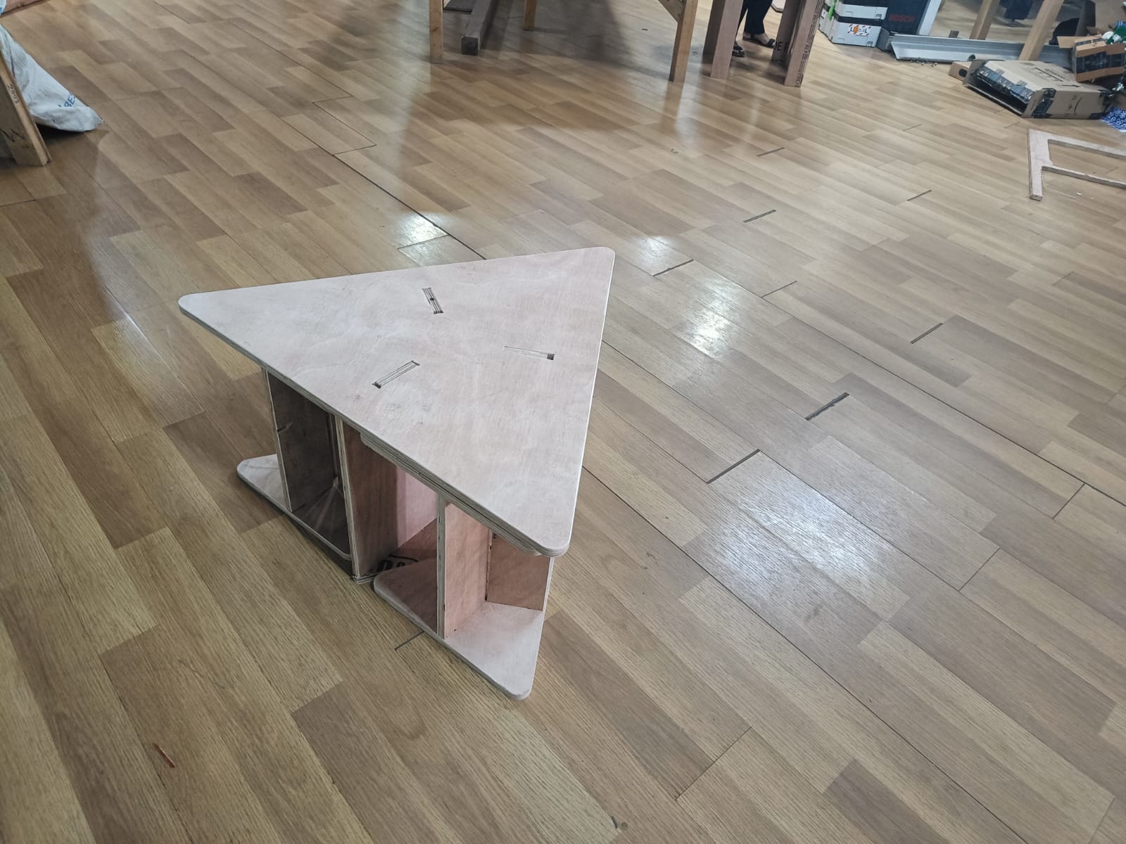
Final Assembled work:
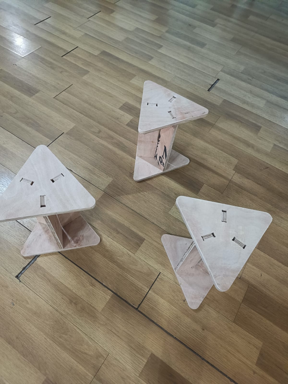
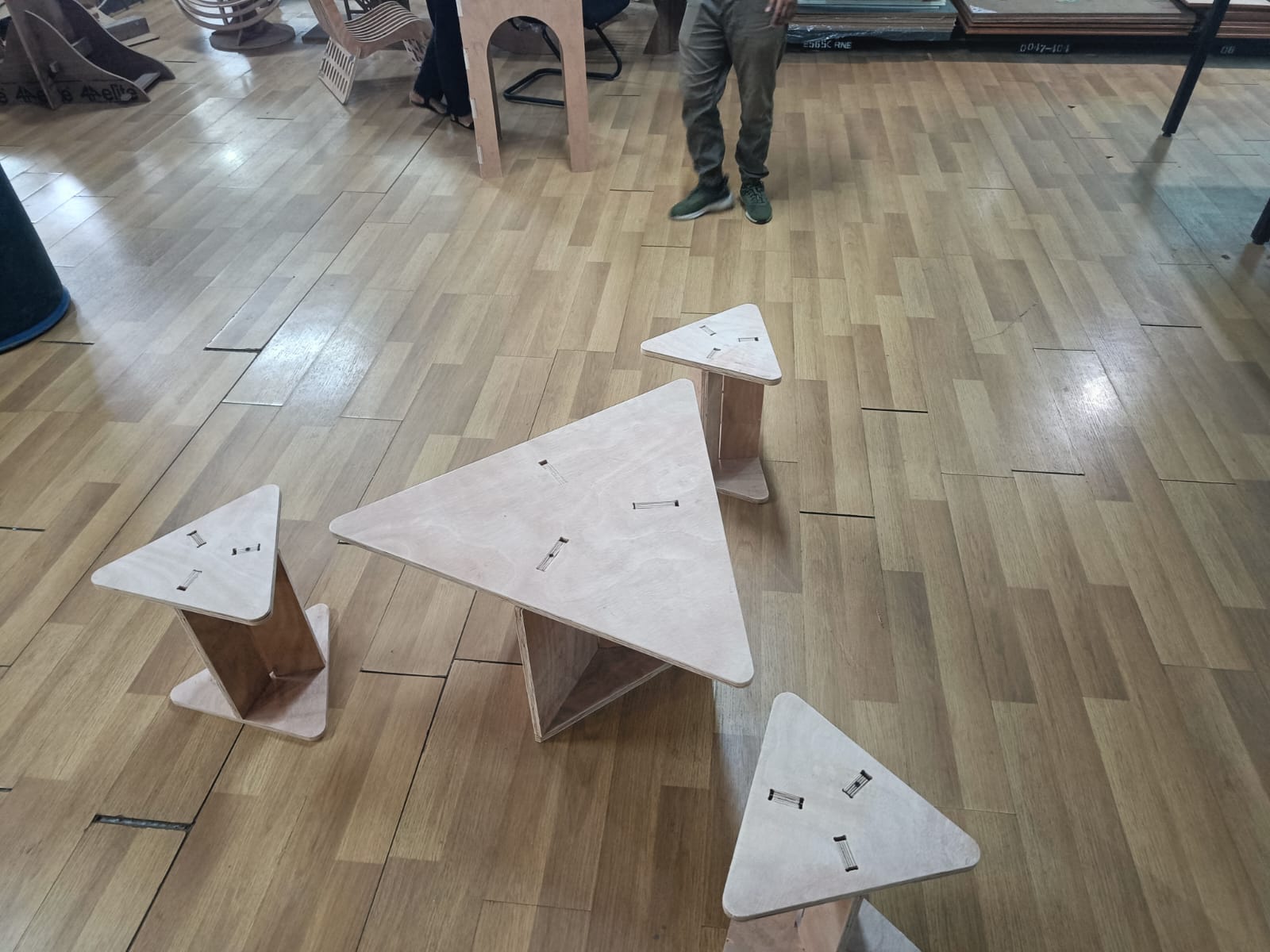
My space efficient 3-seater with stools neatly stacked inside.
A small collaborative discussion on my work with my friends.

Problems I faced:
The fitting was slightly lose at some places as the plywood was of different thicknesses at different places. I fixed it by adding a nail in the cetre to slightly adjust for the thickness.
Shopbot Files: Drilling Files Inner Cuts Outer cutsDXF files for cutting:
Scaled down files for Zund cutting Scaled down Original size DXF for cutting on 8 ft * 4 ft 18mm plywood Original Size Fusion Files: Drilling Files